A first impression of ASRock Rack ALTRAD8UD-1L2T (Ampere Altra)
My other articles on the same topic:
- First (this one): A first impression of ASRock Rack ALTRAD8UD-1L2T (Ampere Altra)
- Second: A quick update on ALTRAD8UD-1L2T (making it work with GPU)
Intro
Over half a year ago, I wrote an article about the 25 Gbit/s network at home. This isn’t the sequel to that story. I’m still collecting material there as I’ve explored a few subjects on various loose ends, but I don’t have enough on any sub-topic to write the next chapter. I promise I will write something about that soon. But a minor spoiler led me here — buying a brand new 64-Core ARM server board.
That board is worth at least a short note (and a potential follow-up with benchmarks and other things I’ll find if there will be anything interesting), mainly because there is not much information about it.

The story begins with a friend messaging me while I was on vacation and travelling and saying, “Hey, have you seen that yet? There is an ARM board in stock in the US! And it comes with a CPU as well”. That was a Newegg Asrock Rack Bundle ALTRAD8UD-1L2T (incl. Ampere Altra Q64–22 and 2U passive cooling, for about 1500$). Coincidentally, at precisely that time, I was thinking about what I wanted to put into colocation at that moment. And hey, it’s ARM, so it should be low-power, right? And I/O capabilities look nice, so why not that? There is a slight complication — newegg doesn’t seem to ship to Switzerland, but it is nothing that can’t be worked around with one of many forwarding services. About a week later, I got it at my doorstep. Time to unpack!
The Board
Unfortunately, I don’t have photos of the actual unpack that I did because I decided to create a video about that, but then messed up with the setup and ended up having no sound and one frame per 10 minutes or something :) However, there is not much to tell. There was a motherboard with CPU pre-installed, I/O Shield, 24-pin ATX to Micro-Fit ATX 4-pin Power Connector adapter, 2 screws for M.2 sockets (each in their own plastic), Quick Starting guide (almost a one-pager about basic setup), and a plastic CPU carrier.
The most mysterious component to me is the plastic carrier, as it was never mentioned in the manual outside of the list of what is included, nor does it fit anywhere. My only idea is that it is somehow supposed to help install the CPU without any shifts or tilts, but as the CPU is pre-installed in the bundle, I’ve decided not to remove it.

Something unique about the bundle is that it comes with a 2U passive cooler, which seems to be something you can’t buy anywhere else. I know three alternative options — a 1U cooler from Supermicro and two coolers from Noctua (U14S and D9S) — with only Supermicro readily available on eBay.

The board itself is what they call Deep Micro-ATX, so it is slightly larger than usual Micro-ATX boards, but not much. It hosts:
- 8 memory slots
- Intel X550 daul-port 10 Gbps NIC
- 4 full-length PCIe slots (two caveats: the first — top two slots are x8 on Altera Altra chips, but they will function as x16 on Altra Max; the second — last slot is not compatible with full-length cards as some of the components will prevent them from functioning)
- 4 Slimline x8 ports, two Oculinks
- a bunch of FAN headers
- 2x M.2 slots (up to 2280)
And so on. So, the board is packed with features in a very compact form factor. Of course, it comes with drawbacks, mainly non-typical power connectors. The official manual from the website says that you can use either an adapter to Micro-Fit ATX that passes standby voltage and PS-ON signal (and ground), or you can directly connect DC-IN 12V to an 8-pin EPS connector. Oh, and you have 3 of those. Yes, 3. And yes, at least consumer PSUs usually don’t have more than 2.
One important thing — the motherboard supports only DDR4 RDIMMs! With UDIMMs, it won’t boot.
What does the manual say about power? Not much:

I’m not a native speaker, so I had trouble understanding what they meant by “Under the lowest power supply, user can freely use…”. Frankly, I still don’t know if they just meant that one cable is enough only if you have Q32–20 CPU (the lowest-end Altra) or they meant something else. However, in practice, board boots are just fine, with only 2 of them plugged in, and performance-wise, I can’t see any difference. Later on, I’ll explain why.
BMC and boot process
It takes about 5 minutes for BMC to boot; if you connect a fan, you can see that it starts to spin because, by default (at least in my case), it came with an “On power loss: power on” setting enabled. What makes it surprising is that the board uses OpenBMC. Honestly, it's the first time I hear someone using it out of the box on production hardware that is not custom.

Login/Password are standard for OpenBMC and are root:0penBmc — later, this was not that obvious, as the manual font choice makes 0 look like a capital-o.
My board had BMC firmware 2.05.00 out of the box. Interestingly enough, on the official website, the latest final BMC firmware is 01.13.00, and there is a Beta Zone where you can get 02.06.00. How to get 2.05.00? I have no idea. What is the changelog between 2.05.00 and 2.06.00? Your guesses are as good as mine. Some problems I’ve experienced with the stock version seem to be fixed in 2.06. One note: When BMC updates, the fans will shut down regardless of the machine's state for a short while. So plan that accordingly.
After the update, it takes some time for BMC to realise what is the current state of the system (similar to the first boot), and while it is in that state, you will see something like this:
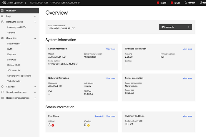
If you think that I’ve redacted the serial number of the board, you would be wrong :) That is the way how it reports it. And yes, it reports power problems while it is running and force-entered BIOS setup:

Until the power cycle, BMC will report power status as “Failure”, and until you remove errors from the logs, system health will be reported as “bad”.
The board doesn’t have many debug LEDs and doesn’t have a typical desktop or workstation motherboard POST code display, so it seems there is no way to debug a failure — or isn’t there?
Going through the manual, I saw section 2.12 “Host Console Debug Code”, which says that if you connect to BMC IP, port 2203, you’ll get some debug information on the early-stage boot process. Let’s try that!
❯ ssh root@10.0.0.92 -p 2203
ssh: connect to host 10.0.0.92 port 2203: Connection refused
…
Well, more ports are mentioned in the manual — 2201 for the ATF console, 2202 for the SCP console, and 22 for BMC. Let’s log in to BMC and check what is listening and where:

Port 2200 is not mentioned in any docs; could it be that there is just a typo?

And yes, it is a typo! If you boot the system when connected to port 2200, you’ll see a console log with some internal information (like memory training results), and you can even debug HW issues that way. For example, here is what it says if you remove the RAM stick:
NOTICE: DRAM FW version 220414
ERROR: NO-DIMM Installed. STOP!
Or let’s install a UDIMM instead of RDIMM:
NOTICE: DRAM FW version 220414
CP: 0ff00900
MEMC param:
mcu_enable_mask = 00000001 [default: 000000ff]
DRAM populated DIMMs:
SK0 MC0 S0: UDIMM[45:0b] 8GB 3200 1R x8 WPBH32D408UWA-8G
CP: 3ff00100
<…>
CP: 00001a06
CP: 00001a06
CP: 00001a06
CP: 00001a06
ERR: 80006940
ERR: 8ff0c700
CP: 3ff00800
ERR: bff0c100
ERROR: SK[0]: 00120001
ERROR: MC[0]: 000100a6
ERROR: DDR initialization failure. Enter safemode…
It will try to boot with it in safe mode, but eventually, it’ll just hang.
During the normal boot process, it will tell what boot stage it is in, and those stages are described in the manual in a POST CODE Table. I’m not sure, but I feel those are standard UEFI codes.
Some quirks in the BMC were not entirely fixed by updating it to 2.06 (it was slightly worse in 2.05), like the sensors page, that reports something which does not always make sense:


Of course, I had a fan connected to a header all that time and running just fine. It is a typical desktop 4-pin Noctua fan, nothing special, but for some reason, the motherboard can’t read its speed, and after you open the Sensors page, it starts blinking a RED LED that indicates “FAN failure”, and it will be blinking all the time until I disconnect the fan, open that page again, it will detect that no fan is present and will stop. Just removing the FAN is not enough. So, I wouldn’t expect it to report the status reliably in case of actual failure. At all.
Some sensors, like “TEMP_TR1”, appear to be not connected to anything, and probably it's fine, but it is just a strange thing to see. What PWR_RCA_VR shows — I don’t know, but the “Current value” is not static at 1024.023W, it fluctuates… ¯\_(ツ)_/¯
Basic functionality is there, Virtual Media and KVM work fine, and this is what matters.

OS and power consumption
There is little to tell here. Installing the OS is similar to installing any other server system — you plug in the ISO over BMC, boot from it, and install it. Debian 12 boots just fine; there were no issues at all, at least for me.
However, there is something we can talk about a bit more — it is power consumption. Linux sensors report CPU and IO power, and for a 64-core CPU, it is impressive even in Idle:
apm_xgene-isa-0000
Adapter: ISA adapter
SoC Temperature: +48.0°C
CPU power: 9.36 W
IO power: 2.51 W
I’ve measured power consumption from a smart socket, basically off the wall and here is what I’ve got:

It is not much. That is when I have one RAM stick (I currently don’t have more) and an NVMe SSD installed, the board is connected to ethernet with two cables (BMC and Network), and one FAN is spinning.
How about a slightly higher CPU load? The best idea I had was to run HPLinpack and try to load the CPU with heavy vectorised FP computations:

That is the highest I managed to get with a CPU-intensive load, and honestly, I’m more than happy with that so far. Of course, if I add more PCIe devices, the IO power draw will go up, and I can probably find a better task than HPLinpack to generate heat. But as a first test, it seems reasonable enough.
And remember what I’ve said about 8-pin EPS connectors and that even one should be enough? That is the cause. A single 8-pin EPS connector is designed to pull up to 150W, which is more than enough to power up this board with a Q64–22 CPU. Yeah, if you’ll look at TDP of other models:

for something like Q64–30 you’ll be on the edge, and for M128–28 it won’t be enough. But for Q64–22? Probably one connector will be fine, so I’ll keep it running with 2 connected so it won’t affect performance and benchmarks.
Instead of conclusion
Honestly, I was slightly afraid when I ordered that board, as there was not much information. If you have ever dealt with ARM SBCs, they are way less usable and more quirky than your typical x86 server. But this one looks relatively mature. Sure, there are problems, but they are rather minor. I probably need to wait for my RAM to arrive and do proper testing. So, more fun awaits! And if you have an idea of what I should test or try on that board — I’m open to ideas, please reach out to me or comment below.
